A brief transfer interruption can stop a production line, darken a critical room, or reset sensitive equipment. The Uptime Institute’s 2024 Annual Outage Analysis reported that 54% of respondents’ most recent significant outages cost more than $100,000; 16% exceeded $1 million. Those figures cover outages broadly, not failures caused specifically by transfer switches. Still, they show why backup power deserves careful planning.
A dual power automatic transfer switch monitors two power sources and transfers a load when the preferred supply fails. Choosing one is not just a matter of matching amperage. Buyers should compare voltage, phase, frequency, pole configuration, transfer timing, short-circuit withstand ratings, operating environment, and compatibility with generators or utility feeds. A switch that looks suitable on a specification sheet may not fit the actual fault level or load behavior. That detail is easy to overlook.
This guide explains how to select a switch around the installation, not just the catalog description. It also considers open- and closed-transition operation, manual bypass needs, maintenance access, controls, and testing. For an authoritative expert quotation, a verifiable source is essential; no source text was provided, so attributing a sentence to a named specialist would risk inventing a quotation. Use the relevant manufacturer documentation and applicable IEC 60947-6-1 requirements to verify the final selection with a qualified electrical professional. A small mismatch can matter.
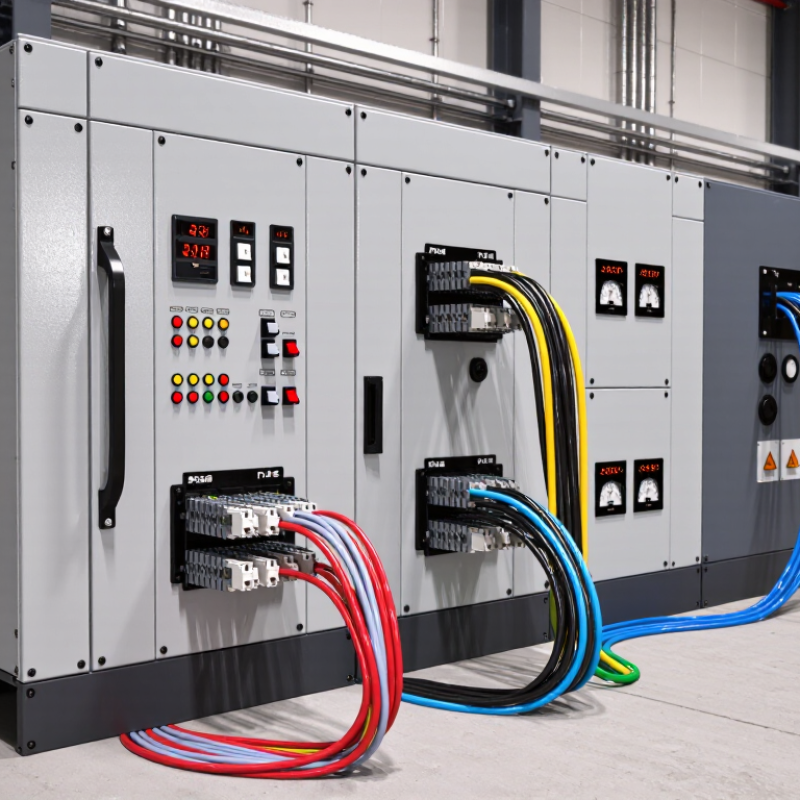
Define the load before choosing a dual power automatic transfer switch. List the equipment that must stay on during an outage, such as a well pump, refrigerator, network equipment, or selected lights. Add each item’s running power, then check its starting demand. Motors can briefly draw much more current when they start. A pump and refrigerator starting together may exceed a generator’s practical capacity. Measure, don’t guess.
Tips: Mark essential circuits on your panel schedule. Note each load’s voltage, phase, and current. Include room for future needs, but avoid sizing around equipment that will never run during an outage.
Next, define what the backup source can actually supply and for how long. Compare its continuous output with the total essential load, and account for the largest starting surge. Decide whether loads will operate together or in stages; a written priority list can prevent overloads. The transfer switch must match the system’s electrical ratings and provide suitable capacity for the connected circuits. These details are easy to overlook on paper. Have a qualified electrical professional verify the load figures, source compatibility, and installation before purchase. Recheck assumptions if you add equipment or change how the space is used.
Choosing a dual power automatic transfer switch begins with its transfer mode. Open transition disconnects the normal source before connecting the backup. It is simple and avoids paralleling sources, but sensitive controls may reset during the brief interruption. Delayed transition adds a pause, useful for motor loads that need voltage to decay. Closed transition briefly overlaps sources, so both supplies must be synchronized and the system must permit that overlap. Faster is not always safer.
Then compare the switching mechanism. Contactor-based units can transfer quickly and suit frequent operation, while circuit-breaker designs provide overcurrent protection within the switching assembly. Check the rated current, short-circuit withstand rating, pole configuration, and whether the neutral must switch. A pump room with large motors may need different settings from a control panel full of sensitive electronics. Site conditions matter.
Reliability has a measurable cost. Uptime Institute’s 2024 Annual Outage Analysis reported that 54% of respondents said their most recent significant outage cost more than $100,000; 16% reported costs above $1 million. That is not proof that one transfer mode prevents outages, but it supports careful selection and testing. Ask an engineer to verify the load sequence, source compatibility, and actual transfer time. A neat specification sheet can still miss an awkward restart behavior.
Choosing a dual power automatic transfer switch starts with the actual supply voltage, not just the number printed on a panel. Check both power sources and confirm whether the system is single-phase or three-phase. A switch rated for the wrong voltage may not transfer power reliably. Small details matter. Compare the switch’s stated operating range with the equipment nameplates and site measurements.
Current rating needs equal care. Add the loads that may run at the same time, then consider brief starting surges from motors, pumps, or compressors. A pump that draws modest current while running can demand much more for a moment at startup. The switch must handle the expected load under its installation conditions. Heat, enclosure space, and frequent operation can affect performance, so a bare number on a label is not the whole story. I would check the specifications twice rather than assume a close rating is good enough.
Pole configuration determines which conductors are transferred. Match the poles to the supply conductors and the installation’s neutral arrangement; some systems require the neutral to switch, while others do not. Grounding and system design matter here. Verify the wiring diagram and have a qualified electrician confirm the choice, especially when the two sources use different grounding arrangements. The neutral is easy to overlook, and that is exactly why it deserves a second look.
How to Choose a Dual Power Automatic Transfer Switch
Choosing a dual power automatic transfer switch means checking what happens when a supply fails, not just its rated current. Confirm that it monitors both sources and transfers only when voltage and frequency meet specified limits. Look for overload and short-circuit coordination, clear separation between sources, and a manual operating method if automatic control fails. The right protection depends on the upstream breaker and connected load; a higher rating alone does not guarantee safety. Check the technical datasheet, not just the product label.
Tips: Before ordering, list each connected load, its starting current, and its tolerance for brief interruptions. Compare these details with the switch’s rated current, number of poles, switching time, and permitted source arrangement. Measure the panel space and cable entry points, too. A unit may fit electrically but leave little room for safe wiring or inspection. That detail is easy to miss.
Installation conditions matter as much as protection features. Check whether the enclosure suits local dust, moisture, heat, and vibration. Allow clearance for ventilation and servicing. Verify cable size, terminal capacity, grounding, and source compatibility against the manufacturer’s instructions. Have a qualified electrician assess the system and test transfer behavior under controlled conditions. A quick visual check is not enough. Site conditions can change, and plans sometimes need revision.
Illustrative single-phase sizing example: Compare calculated load current with a 25% sizing allowance and the next listed ATS current rating.
Example assumes 230 V and a 0.9 power factor, using I = P ÷ (V × power factor). The 32 A, 63 A, and 100 A ratings are example standard ratings, not a universal recommendation. Confirm the actual load, local electrical requirements, short-circuit protection and coordination, phase and pole configuration, neutral switching, voltage and frequency, ambient temperature, enclosure rating, and installation clearances before selecting an ATS.
How to Choose a Dual Power Automatic Transfer Switch
Assess Standards, Reliability, and Maintenance Needs
Check which electrical standards apply at the installation site, then verify the switch’s documented ratings. Look for clear details on voltage, current, short-circuit withstand, and transfer time. These figures should match the actual supply and connected loads, not just a catalog example. If critical equipment cannot tolerate a brief interruption, confirm the transfer behavior with a qualified electrical professional. A certificate alone does not answer every site-specific question.
Reliability depends on more than a sturdy enclosure. Ask how the unit detects a failed source, prevents both supplies from connecting at once, and signals alarms. Consider the environment, too: dust, heat, vibration, and frequent switching can affect performance. It is tempting to trust a polished datasheet, but real operating conditions are messier. Review the test records and failure-response details before comparing prices. Small details matter.
Maintenance needs should be practical and clearly documented. Check whether inspections can be completed safely, and whether contact wear, loose terminals, and control settings are accessible for review. The maintenance schedule should reflect operating frequency and site conditions. Keep a dated log. Record transfer tests, alarms, and repairs so changes become visible over time. That habit helps. Even a well-rated switch can become unreliable when checks are skipped or records are incomplete.
| Assessment Dimension | What to Check | Practical Selection Guidance | Evidence to Request |
|---|---|---|---|
| Applicable standards and codes | Confirm which product standards and installation rules apply in the project’s jurisdiction and to the intended application. | Common references include UL 1008 in the United States and IEC 60947-6-1 internationally. NFPA 110 and applicable electrical codes may also govern emergency or standby power installations. Requirements vary by location and system type. | Applicable certification or conformity documentation, product markings, and confirmation from the project engineer or authority having jurisdiction. |
| Voltage, current, and frequency | Match the switch’s ratings to the system voltage, phase, frequency, and continuous load current. | Choose ratings suitable for the actual installation and expected load. Check whether the equipment is rated for the system’s grounding arrangement and any neutral switching requirements. | Rating plate, wiring diagrams, and documentation showing the tested electrical ratings. |
| Short-circuit withstand and protection | Compare the available fault current at the installation point with the switch’s short-circuit ratings and the specified upstream protective device. | Verify the complete tested combination where a rating depends on a particular protective device. Do not assume that the switch’s normal current rating establishes its short-circuit capability. | Short-circuit rating data and coordination information for the specified overcurrent protective device. |
| Transfer method and load compatibility | Determine whether open-transition, delayed-transition, or closed-transition operation is required and permitted. | Open transition briefly disconnects the load from one source before connection to the other. Closed transition briefly parallels sources and requires compatible sources and appropriate controls. Transfer time depends on the equipment, settings, and operating conditions. | Sequence-of-operation description, transfer-time data under stated conditions, and confirmation of compatibility with the load and power sources. |
| Reliability and operating environment | Review mechanism design, control-power arrangements, enclosure protection, operating temperature, and expected switching duty. | Select an enclosure and environmental rating suitable for the installation location. Consider source-quality monitoring, manual operation provisions, and the consequences of a failed transfer for the served loads. | Environmental ratings, operating limits, control schematics, endurance or switching-duty information, and functional test procedures. |
| Maintenance and testing | Assess inspection access, available service documentation, test facilities, and the maintenance tasks required by the applicable rules. | Follow the equipment instructions and local requirements. For systems governed by NFPA 110, apply the relevant inspection, testing, and maintenance provisions for the installation. Establish a documented schedule appropriate to the system and operating conditions. | Maintenance manual, recommended inspection and test procedures, parts information, and a recordkeeping template or checklist. |
| Controls, alarms, and system integration | Check source sensing, transfer and retransfer settings, alarm contacts, remote monitoring, and generator start interfaces. | Confirm settings and interfaces match the source equipment and facility control system. Review time delays and retransfer behavior to avoid unwanted switching or interruption of sensitive loads. | Control wiring diagrams, adjustable-setting ranges, alarm descriptions, and commissioning test steps. |