How to Choose the Right Electrical Transfer Switch?
Choosing the right electrical transfer switch begins with the load, not the product brochure. A hospital, data center, factory, and small office face very different risks. Each site needs a careful review of voltage, phase, amperage, fault current, switching speed, and generator compatibility. One overlooked motor can exceed the switch’s rating during startup. That detail matters.
Industry data shows why this decision deserves engineering discipline. MarketsandMarkets projects the global automatic transfer switch market to grow from approximately USD 1.3 billion in 2023 to USD 1.8 billion by 2028, at about 6.7% annually. The U.S. Energy Information Administration also reports that power interruptions remain a recurring operational concern, especially when major weather events are included. These figures do not select a switch for you. They show the scale of the reliability problem.
Mike Holt, a respected electrical-code educator, explains the core function simply: “A transfer switch transfers the electrical load from one power source to another.” The wording is basic. The application is not. A suitable electrical transfer switch must coordinate with protective devices, emergency power controls, maintenance procedures, and local code requirements. Automatic or manual operation is only one decision. Open-transition switching may protect equipment from source overlap, while closed-transition designs can reduce interruption time. Neither option is universally better. A rushed specification may look acceptable on paper, yet fail beside a real generator, crowded panel, or unbalanced load. This guide examines those practical choices, including the uncomfortable gaps engineers sometimes discover after installation.
What an Electrical Transfer Switch Does
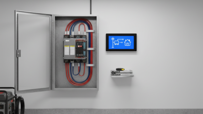
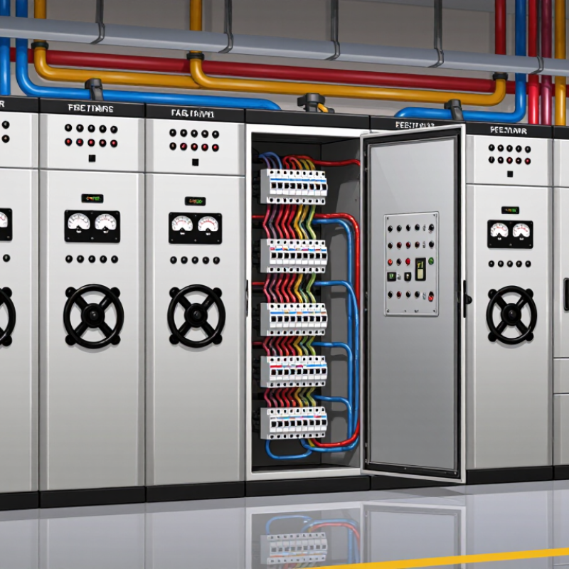
An electrical transfer switch connects a facility to two power sources, usually utility power and a standby generator. Its main job is source selection. During an outage, an automatic model senses voltage loss and transfers selected loads to the generator. When utility power returns, it transfers them back after a controlled delay.
This process protects equipment and helps prevent dangerous backfeed into utility lines. It also separates essential circuits, such as emergency lighting, refrigeration, pumps, and medical equipment, from nonessential loads. Open-transition switches briefly disconnect both sources before connecting the second source. Closed-transition models may overlap sources for a short period, but they require compatible equipment and careful engineering. In practical installations, incorrect neutral handling can create nuisance trips or unsafe voltage conditions.
Tips: Match the switch rating to the connected load, voltage, fault current, and generator capacity. Check whether the equipment needs automatic or manual operation. Ask a qualified electrician to verify grounding, phase sequence, enclosure protection, and local code requirements. A switch may be correctly sized and still perform poorly if the generator starts too slowly. That detail is easy to miss. Keep records of testing, inspect terminals for heat marks, and exercise the transfer mechanism regularly. Real conditions matter more than a catalog specification.
How to Assess Your Power and Load Requirements
Choosing an electrical transfer switch starts with a measured load assessment, not a guess based on panel size. List every connected load, including lighting, controls, pumps, heating equipment, and battery chargers. Record normal running watts and voltage for each circuit. Then identify motor starting current, inrush current, and loads that may operate simultaneously.
The U.S. Department of Energy reports that data centers could consume 325–580 terawatt-hours of electricity annually by 2028. This projection shows why future expansion deserves attention during switch selection. Berkeley Lab’s 2024 United States Data Center Energy Usage Report also estimated 176 terawatt-hours of data-center consumption in 2023. Your site may be smaller, but sudden load growth can still exceed an undersized transfer switch.
Calculate the expected operating load first. Add starting demand separately, especially for compressors, pumps, and fans. A 40-kilowatt running load may require much more during motor acceleration. Check the generator’s available starting capacity, not only its continuous rating. Include nonlinear loads, because power supplies and variable-speed drives can increase harmonic heating. A practical field review should compare measured demand with design calculations. Clamp-meter readings help reveal real operating behavior.
Leave room for growth.
However, a large safety margin is not automatically safer. Oversizing can reduce monitoring accuracy and increase project cost. Recheck the calculation after seasonal testing, equipment changes, and emergency drills. The final rating should match the actual load profile and applicable electrical codes.
How to Choose the Right Electrical Transfer Switch? — How to Assess Your Power and Load Requirements
| Application Scenario |
System Voltage |
Phase / Frequency |
Connected Load |
Estimated Demand Load |
Largest Motor or Inrush Load |
Recommended Switch Rating |
Recommended Poles |
Transition Type |
Selection Considerations |
| Small residential backup |
120/240 V |
Single-phase / 60 Hz |
8 kW |
5.6 kW
≈ 23 A at 240 V |
1.5 hp well pump
Approx. 4–6 times running current during start |
100 A minimum |
2-pole |
Open transition |
Allow space for future circuits. Confirm that the generator can start the pump without excessive voltage drop. |
| Large residence with electric heating |
120/240 V |
Single-phase / 60 Hz |
24 kW |
16.8 kW
≈ 70 A at 240 V |
4-ton air-conditioning compressor
High starting current |
200 A minimum |
2-pole |
Open transition |
Use load management or staged starting if the generator cannot support heating, cooling, and motor loads simultaneously. |
| Small office or retail unit |
120/208 V |
Three-phase / 60 Hz |
35 kVA |
24.5 kVA
≈ 68 A at 208 V |
5 hp ventilation motor |
100 A minimum |
3-pole or 4-pole |
Open transition |
Choose 4-pole switching when the neutral must be separately switched or when the separately derived source requires neutral isolation. |
| Commercial refrigeration system |
208/120 V |
Three-phase / 60 Hz |
60 kVA |
42 kVA
≈ 117 A at 208 V |
15 hp compressor motor
High locked-rotor current |
200 A minimum |
3-pole or 4-pole |
Open transition |
Verify generator transient response and compressor starting capability. Consider time delays between multiple compressors. |
| Light industrial workshop |
480/277 V |
Three-phase / 60 Hz |
150 kVA |
105 kVA
≈ 126 A at 480 V |
30 hp induction motor
Typical starting current: 5–7 times full-load current |
200 A minimum |
3-pole |
Open transition |
Check motor-starting kVA, feeder protection, short-circuit rating, and coordination with the upstream overcurrent device. |
| Data and communications room |
208/120 V |
Three-phase / 60 Hz |
100 kVA |
70 kVA
≈ 194 A at 208 V |
UPS rectifiers and cooling equipment
Possible harmonic currents |
250 A minimum |
4-pole where required |
Closed or delayed transition |
Evaluate no-break requirements, bypass arrangements, neutral loading, harmonics, and the transfer switch’s withstand and closing ratings. |
| Healthcare critical branch |
480/277 V |
Three-phase / 60 Hz |
300 kVA |
210 kVA
≈ 253 A at 480 V |
Medical air compressors, HVAC motors, and elevators |
400 A minimum |
3-pole or 4-pole |
Open or delayed transition |
Use a listed life-safety or critical-branch configuration where applicable. Confirm transfer time, bypass isolation, testing, and code requirements. |
| Industrial process line |
480 V |
Three-phase / 60 Hz |
500 kVA |
350 kVA
≈ 421 A at 480 V |
75 hp conveyor and hydraulic motors |
600 A minimum |
3-pole |
Delayed or closed transition |
Assess process continuity, motor acceleration, utility paralleling restrictions, available fault current, and automatic load shedding. |
Planning reference: Demand load is illustrated at approximately 70% of connected load. Final transfer-switch sizing must be verified using measured demand, continuous-load requirements, motor-starting data, conductor ampacity, overcurrent protection, available fault current, and applicable electrical codes.
How to Confirm Compatibility, Compliance, and Maintenance Needs
Choosing an electrical transfer switch starts with compatibility, not appearance. Confirm the system voltage, phase arrangement, frequency, ampere rating, and available fault current. The switch must match the generator and the building’s distribution equipment. Fit is not enough.
Compare the switch’s wiring diagram with the actual installation. Check neutral switching, grounding arrangements, bypass features, and control wiring before ordering. A qualified electrical professional should verify these details against current local codes and inspection requirements. Certification markings and test documentation matter, but paperwork alone cannot correct poor installation. Leave room for cable bending, heat dissipation, and safe access to terminals. A cramped enclosure may pass an initial review yet create problems during service.
Maintenance needs should be practical and visible. Ask how often the mechanism requires inspection, exercise the transfer function under controlled conditions, and record switching results. Inspect terminals for looseness, discoloration, moisture, or unusual heat. Battery condition, control fuses, alarms, and interlocks also deserve attention. Document everything.
A useful maintenance schedule depends on load, environment, and emergency importance. Dusty rooms may need more frequent cleaning, while outdoor equipment requires careful enclosure checks. I have seen schedules copied from manuals without considering actual site conditions. That is a weakness. Revisit the plan after the first operating season, and adjust it when testing reveals delays, nuisance alarms, or difficult access. Reliability is confirmed through evidence, not confidence alone.