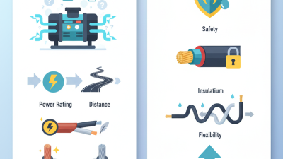
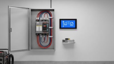
As global power projects become more demanding, choosing the right generator cable requires more than comparing prices. In 2026, buyers must consider load capacity, insulation, flexibility, operating temperature, installation conditions, and destination-market requirements. A cable running across a dry warehouse floor faces different risks from one exposed to rain, oil, vibration, or repeated movement.
A generator cable must transfer power safely under real working conditions. Common options include flexible rubber cables, thermoplastic cables, armored designs, and heavy-duty welding-style cables for selected applications. Each type has practical strengths and limits. For example, a flexible rubber cable may handle frequent coiling better, while an armored cable can provide added mechanical protection in fixed installations. The correct choice depends on current demand, cable length, voltage, connector design, and environmental exposure.
This guide draws on procurement practice, technical documentation, and field-based selection principles. It explains how professional buyers can review conductor material, cross-sectional area, insulation compounds, temperature ratings, and certification records. Product labels matter. So do factory test reports, traceability, and clear quality-control procedures. A lower price can become expensive when voltage drop causes overheating or unplanned downtime.
No checklist is perfect. Some buyers still focus only on ampacity, and that shortcut can fail. Installation layout, bending radius, storage conditions, and maintenance habits deserve equal attention. Regional standards may also differ, so documentation should be verified before shipment. We will compare generator cable types, identify suitable use cases, and highlight questions worth asking suppliers. The goal is not to promote one universal cable. It is to support safer, more reliable purchasing decisions for global energy projects.
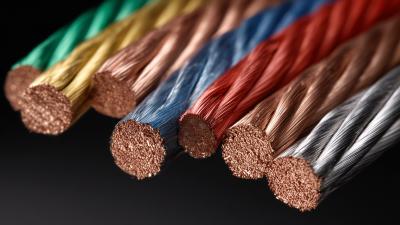
Generator cable selection starts with the conductor, not the outer jacket. IEC 60228 defines conductor classes by flexibility and construction. Class 1 uses solid conductors. Class 2 uses stranded conductors with limited flexibility. Class 5 and Class 6 support flexible and highly flexible applications. Temporary generator connections usually need better movement tolerance than fixed installations.
Voltage markings need careful reading. A 0.6/1 kV cable is generally rated for 600 V between conductor and earth, and 1,000 V between conductors. This differs from simply calling a cable “600 V–1 kV.” The insulation system, temperature rating, installation method, and national requirements still matter. A cable may meet the voltage number but fail under repeated bending, heat, moisture, or abrasion. That detail is easy to miss.
Tips: Check the printed voltage designation, IEC 60228 conductor class, cross-sectional area, and conductor resistance. Request routine test records and confirm the cable’s minimum bending radius. For mobile generators, inspect the jacket after every relocation. Small cuts can grow quickly. Independent verification is useful, though it adds time and cost. One imperfect assumption remains common: a larger conductor is not automatically the safest choice. Compatibility with terminals, protection devices, and actual load conditions must be checked by a qualified electrical professional.
For 2026 generator installations, copper and aluminum cables serve different priorities. The Copper Development Association reports annealed copper at 100% IACS conductivity. Aluminum reaches about 61% IACS at 20°C. That difference affects cable sizing, heat, and voltage drop.
Copper carries the same current with a smaller conductor. It also handles repeated terminations better. A technician can route it through a tight generator cabinet with less bending resistance. Aluminum is much lighter. The Aluminum Association reports densities of approximately 2.70 g/cm³ for aluminum and 8.96 g/cm³ for copper. With equivalent electrical resistance, aluminum conductors can weigh roughly half as much. That matters for long temporary feeders and difficult rooftop installations.
However, aluminum usually needs a larger cross-sectional area. Its oxide layer and higher thermal expansion demand correctly rated lugs, preparation, and torque control. IEC 60228 conductor-resistance requirements still apply, but local installation rules can change acceptable cable sizes. Field experience shows that loose terminations create more risk than the metal choice itself. I would not treat aluminum as a cheap copper substitute. That assumption is too simple. A poorly prepared aluminum connection may heat under continuous generator load, while an oversized cable can complicate routing and cost. Buyers should compare resistance, weight, bend radius, termination hardware, ambient temperature, and maintenance access before ordering.
The comparison below uses commonly accepted material properties at approximately 20°C. Actual cable selection must follow the applicable local code, installation method, ambient temperature, grouping, voltage-drop limit, short-circuit withstand, and generator protection requirements.
| Evaluation Dimension | Copper Cable | Aluminum Cable | Practical Implication for Generator Applications |
|---|---|---|---|
| Electrical conductivity at 20°C | Approximately 100% IACS; resistivity about 0.01724 Ω·mm²/m. | Approximately 61% IACS; resistivity about 0.02826 Ω·mm²/m. | Copper provides lower resistance for the same cross-sectional area. Aluminum generally requires a larger conductor to achieve comparable electrical performance. |
| Relative conductor density | About 8.96 g/cm³. | About 2.70 g/cm³. | Aluminum conductors can substantially reduce cable weight, especially on long feeder runs and temporary generator installations. |
| Equivalent conductor area for similar resistance | Reference: 1.00 unit of cross-sectional area. | Approximately 1.64 times the copper area for similar resistance at the same conductor length and temperature. | A larger aluminum conductor or cable size may be needed. The final size must be selected from verified ampacity and voltage-drop calculations. |
| Approximate conductor mass at similar resistance | Reference: 1.00 unit of mass. | Approximately 0.49 times the copper conductor mass when sized for similar resistance. | Aluminum can improve transport and handling efficiency even after allowing for its larger cross-sectional area. |
| Voltage-drop behavior | Lower resistance per unit area; generally easier to keep voltage drop low in compact cable sizes. | Higher resistance per unit area; voltage-drop calculations are particularly important on long runs. | For sensitive generator loads, compare calculated voltage drop during starting and steady-state operation, not only the cable ampacity. |
| Flexibility and handling | Usually more flexible and easier to terminate in compact generator switchboards, plugs, and lugs. | Typically less flexible at an equivalent electrical rating because the conductor is larger; alloy and stranding affect handling. | Copper is often preferred for frequently moved temporary cables. Aluminum is more attractive for fixed or infrequently relocated feeders. |
| Termination requirements | Standard copper-rated lugs and terminals are widely available. Connections still require correct torque and preparation. | Requires terminals and connectors specifically rated for aluminum or dual-metal use, plus correct oxide-control and torque procedures where specified. | Improper aluminum termination can increase contact resistance and heating. Connector compatibility is a critical purchasing requirement. |
| Thermal expansion | Linear expansion coefficient is approximately 16.5 × 10⁻⁶/°C. | Linear expansion coefficient is approximately 23.1 × 10⁻⁶/°C. | Aluminum connections may experience greater movement during load and temperature cycles, so suitable terminals, support, and retightening practices are important. |
| Corrosion considerations | Generally durable, but galvanic corrosion can occur when copper contacts dissimilar metals in moisture. | Forms a tenacious oxide layer; exposed or poorly prepared interfaces can increase contact resistance. | Use compatible plated or bi-metal connectors where required, protect terminations from moisture, and follow the connector manufacturer’s preparation instructions. |
| Short-circuit performance | High conductivity supports strong short-duration fault performance when correctly sized and protected. | Can also meet short-circuit requirements when correctly sized; larger area and termination quality must be considered. | Check the cable’s short-circuit withstand against the generator fault current and protective-device clearing time. |
| Common generator cable construction | Flexible stranded single-core cables, multicore power cables, welding-style flexible cables, and fixed-installation power cables. | Stranded single-core or multicore feeder cables, commonly used for fixed distribution and long-distance power runs. | Select the construction according to movement, bending radius, weather exposure, installation route, and required mechanical protection. |
| Temporary generator connection | Often the practical choice for repeated setup, compact connections, and high flexibility. | Suitable when weight reduction is important and the cable is installed with adequate support and approved terminations. | For temporary use, verify abrasion resistance, oil and weather resistance, bend radius, connector rating, and protection against mechanical damage. |
| Long fixed feeder | Technically effective but may be heavy and more expensive to transport at large sizes. | Often advantageous for long, fixed, high-current feeders because of lower weight and larger conductor-area options. | Evaluate total installed cost, including cable supports, lugs, termination labor, voltage drop, and maintenance—not conductor price alone. |
| Installation space | Smaller conductor size can simplify tight switchgear, distribution panels, and generator output connections. | Requires more physical space for an equivalent resistance rating and may need larger bending radii and cable glands. | Confirm enclosure entry dimensions, lug barrel capacity, phase spacing, bending radius, and heat dissipation before ordering. |
| Typical decision priority | Best when flexibility, compactness, frequent handling, and simple termination are priorities. | Best when low weight, long cable routes, and fixed installation are priorities. | Neither material is universally superior; the correct choice depends on current, distance, installation method, connection technology, and lifecycle cost. |
Note: IACS means International Annealed Copper Standard. Ampacity values are not shown because they vary significantly with conductor size, insulation temperature rating, installation method, ambient conditions, conductor grouping, and national or regional electrical standards.
Generator cable selection starts with load current, not cable appearance. Calculate I = P ÷ (V × power factor), then include motor starting current and continuous-load rules. A 10 kW, 230 V, unity-power-factor load draws about 43.5 A. At 400 V, it draws about 25 A. Small differences matter.
Use the 90°C ampacity column only for derating and correction calculations. The final allowable ampacity must still satisfy the cable’s terminal temperature rating. NFPA 70, 2023 Edition, Table 310.16, lists copper conductor ampacities by insulation temperature and installation condition. IEC 60364-5-52 also requires correction for grouping, ambient temperature, and installation method. A cable rated at 90°C is not automatically safe at 90°C. That assumption causes trouble.
Voltage drop deserves equal attention. A 3% design limit means only 6.9 V at 230 V, or 12 V at 400 V. Long generator runs can exceed this quickly, especially during motor starting. Use conductor resistance, route length, phase arrangement, and power factor in the calculation. For single-phase circuits, remember the current travels out and back. Double the distance.
Check the actual route.
I have seen cable schedules pass an ampacity check but fail under starting load. Recalculate with real length, bundled cables, high ambient heat, and the generator’s transient behavior. The cleanest spreadsheet can still be wrong. Keep a margin where practical, but do not replace engineering verification with guesswork.
Flexible generator cables must survive movement, heat, moisture, and rough handling. The right choice depends on current, voltage, length, and installation conditions. IEC 60502-1 supports power-cable designs with suitable insulation and voltage ratings, but it does not automatically approve every flexible generator connection. Buyers should verify conductor class, bending radius, and termination requirements before ordering. NEC 400 addresses flexible cords and cables in North American applications, including permitted uses and protection rules. Local electrical authorities may still require additional testing.
Tips: Check the cable jacket for sunlight, oil, abrasion, and water resistance. Measure the longest working distance, not the shortest route. Select a larger conductor when voltage drop becomes significant. Avoid tightly coiling a live cable. It can heat internally.
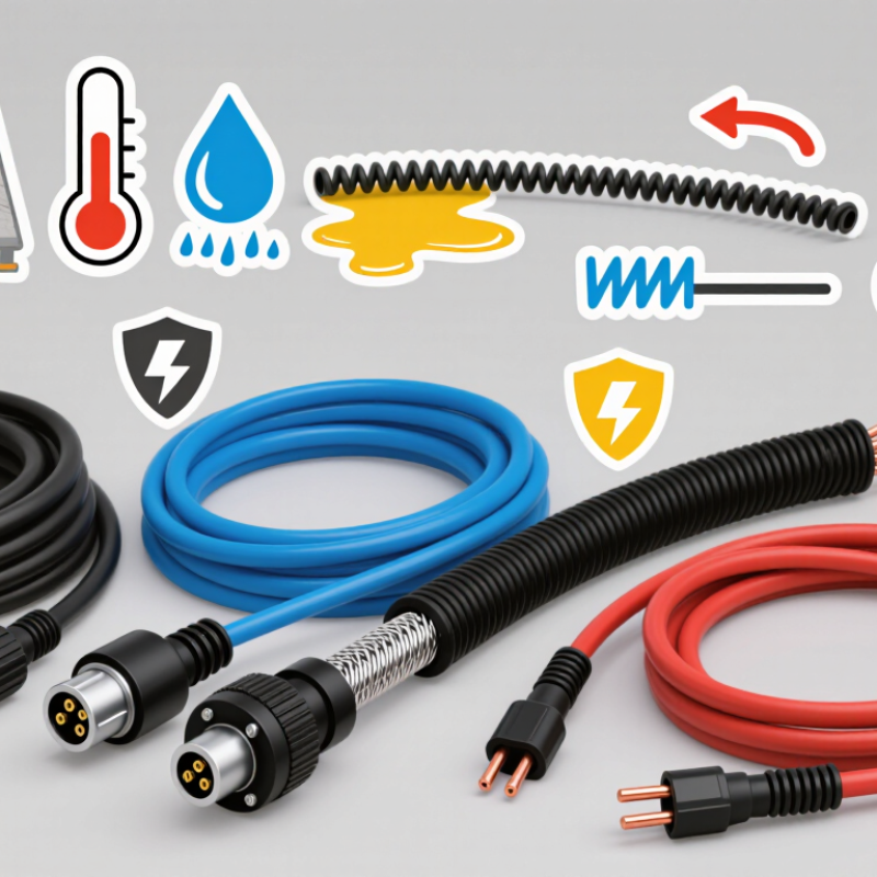
Outdoor durability is more than a thick black jacket. A reliable cable should remain flexible in cold weather and resist cracking under strong sunlight. Its connectors need firm strain relief, sealed contacts, and secure locking features. In field work, dragging cables across gravel often causes damage before electrical aging appears. I have seen users focus on ampacity while ignoring bending stress. That choice can shorten service life. For global projects, request test reports, conductor details, temperature ratings, and clear compliance documentation. Standards are valuable, but they cannot replace a site-specific inspection.
Choosing generator cables for global use requires more than matching the connector shape. Check the generator’s voltage, frequency, rated current, and outlet configuration. Plug standards differ across regions, even when two connectors look similar. Confirm the plug and socket ratings before ordering. A cable rated for outdoor work should also resist moisture, abrasion, oil, and repeated bending.
IP ratings deserve careful reading. IP44 may protect against splashing water, while IP67 offers stronger dust protection and temporary immersion resistance. However, an IP rating may apply only to the connector assembly, not the entire cable. That detail is easy to miss. Cable size should match current, cable length, ambient temperature, and acceptable voltage drop. A thin cable can become hot during continuous loads. It may look perfectly normal.
Certifications should come from recognized testing organizations in the target market. Ask for current test reports, conformity documents, and traceable cable specifications. Do not rely only on printed symbols. Requirements can vary for construction sites, temporary events, agricultural equipment, and emergency power systems. Flexible rubber-insulated cables often suit demanding outdoor movement, while heavy-duty thermoplastic options may fit controlled environments. Keep the cable off standing water and away from sharp edges. My checklist once focused heavily on the plug, but ignored storage temperature. That was a useful correction. Global purchasing needs both paperwork and practical site review.