How to Choose the Best PCAP Touch Screen?
Choosing the best PCAP Touch screen starts with the task it must perform, not the largest number on a product sheet. A kiosk in a bright lobby faces different demands from a control panel beside a sink. Consider screen size, glass thickness, expected touch count, and the gloves users may wear. Small details matter. A thick cover lens can affect sensitivity, while sunlight may make an otherwise clear display hard to read. These trade-offs deserve attention before a design is fixed.
Touch-technology analyst Geoff Walker’s published work offers a useful principle, paraphrased here: select the touch system for its real operating environment, not the specification sheet alone. That means testing the intended controller, display, cover glass, and firmware together. Check response near the edges. Try wet fingers if the device may encounter splashes. Test the gloves people will actually use, not just one convenient pair. PCAP Touch performance depends on the full assembly. A component can look excellent in isolation and still disappoint when integrated. That happens. This guide will compare the key selection criteria, including durability, optical clarity, multi-touch behavior, and integration support. It will also point out where specifications can mislead. No single panel suits every project. A careful shortlist, followed by hands-on testing, is usually more useful than a quick purchase based on price alone. Even then, field conditions can expose surprises, so leave room to revise assumptions.
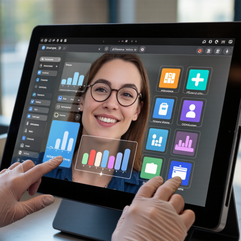
Define PCAP Touch Technology and Its Typical 10-Point Multi-Touch Capability
Projected capacitive (PCAP) touch technology detects changes in an electrical field across a sensor grid. When a finger approaches the glass, it alters the capacitance at nearby electrodes. A controller reads those changes and calculates the touch position. The sensor usually sits behind a protective glass surface, so the display has no moving button layer. It feels immediate.
A typical 10-point PCAP screen can track up to ten touch locations at once. That allows two hands to pinch, rotate, or move several on-screen objects together. “Ten-point” describes the controller’s reported touch capacity, not a guarantee that every setup will handle ten touches equally well. Performance can vary with the controller, software, screen size, and electrical noise. The number can mislead.
When choosing a screen, check whether its touch controller and operating system support the gestures your application needs. Test with real fingers, not only a stylus, and try simultaneous touches near the edges. Gloves, moisture, or a thick cover may affect response, depending on the design. A quick bench test often reveals missed or drifting points. I would not rely on the specification alone; it is easy to overlook how the screen behaves in its actual enclosure.
Match Cover Glass and Optical Transmission, Often Rated at 90% or Higher
When choosing a PCAP touch screen, check whether the 90% or higher transmission rating applies to the cover glass alone or the complete optical stack. The distinction matters. A touch module also includes adhesive, sensor layers, and sometimes anti-glare coatings. Each layer can reduce the light reaching the display or add reflections.
As a simple illustration, layers transmitting 92%, 99%, and 96% transmit about 87% together, before other losses. Small differences matter.
Ask for a measured value, test conditions, and the tested sample configuration. ASTM D1003-21 describes methods for measuring luminous transmittance and haze; ISO 13468-1:2019 provides a method for total luminous transmittance of transparent materials. These standards help make supplier figures more comparable, though they do not guarantee a particular screen performance.
Inspect the panel under bright office lighting, then at an angle. Look for washed-out colors, reflected ceiling lights, and haze around small text. A clear glass sample can look excellent on its own, yet perform differently after lamination. I would verify the assembled screen, not just the glass datasheet.
One caveat: “90%” is not meaningful without knowing what was measured.
Assess Controller Support for Gloves, Moisture, and Electrical Noise
A PCAP touch screen depends on its controller as much as its glass. Check whether the controller supports the glove types people will actually wear. Thin nitrile gloves, thick work gloves, and damp fingertips can produce very different results.
A bare-finger demo proves little. Test with the intended gloves, at normal operating speed, and watch for missed taps or unwanted touches.
Ask whether sensitivity can be adjusted without making the screen trigger too easily. Sensitivity higher is not automatically better.
Moisture needs a realistic test, too. Light droplets, a wet sleeve, and a steady stream of water are different conditions. Confirm how the controller behaves in the environment you expect, and whether wiping the screen causes false input.
Electrical noise matters near motors, power converters, and long cable runs. Review the controller’s noise-immunity design and test the assembled system, not just the panel on a bench. Small grounding or cable changes can affect performance. This is easy to overlook.
I would not rely on a single successful test; repeat checks after installation, because real conditions are rarely as tidy as a specification sheet.
Choose a Compatible Interface, Such as USB or I²C
A PCAP touch screen’s interface should match the host, cable, and response requirements, not just the connector shape. The USB 2.0 specification lists 12 Mbps for full-speed and 480 Mbps for high-speed links. These figures describe link capacity, not the touch controller’s actual report rate. USB can carry power and touch data over one cable, which simplifies a kiosk or test setup. Check the controller’s operating voltage, driver support, and connector pinout before ordering. A familiar plug does not guarantee compatibility.
I²C suits short connections between a touch controller and a nearby processor. The I²C-bus specification UM10204 defines standard-mode operation at 100 kbit/s and fast-mode operation at 400 kbit/s; faster modes are also specified. The interface uses fewer signal lines than USB, but needs correct pull-up resistors and careful board routing. On a compact board, that can be tidy. Across a long cable, signal quality may become the weak point. Not always obvious. Compare the screen’s report rate with the host’s polling method, then test the actual cable and controller together. Specification limits help, but real hardware can still surprise you.
Choosing a PCAP Touch Screen Interface: USB vs. I²C
USB 2.0 Full-Speed has a higher nominal data rate than I²C High-speed mode, but the best choice depends on the touch controller, host support, wiring, and system design. Check the controller’s supported interface and confirm compatibility before selecting a screen.
Check ESD Immunity Against IEC 61000-4-2 Level 4: 8 kV Contact, 15 kV Air
When choosing a PCAP touch screen, check its ESD test evidence, not just a “Level 4” claim. The IEC 61000-4-2 standard defines Level 4 as 8 kV contact discharge and 15 kV air discharge. Ask for the laboratory report showing the tested screen assembly, discharge points, test conditions, and results. A bare panel may behave differently once mounted behind a metal bezel.
In practical evaluation, inspect the bezel, connector openings, and cable path. These are common places for discharge to couple into touch circuitry. A screen may remain lit but register false touches, freeze briefly, or need a reset. Small failures matter. The IEC test levels are useful benchmarks, but they do not guarantee immunity in every installation. Grounding, enclosure design, and nearby equipment can change the outcome.
Compare reports using the same test method and documented acceptance criteria. Confirm that both contact and air tests were performed at the stated Level 4 voltages. Also ask whether the touchscreen recovered without unintended input after each discharge. This detail is easy to miss. In the field, a test setup rarely matches the final machine perfectly, so review the report critically and validate the assembled product under realistic conditions.